Graduate Studio

#27: Ends of the Semesters

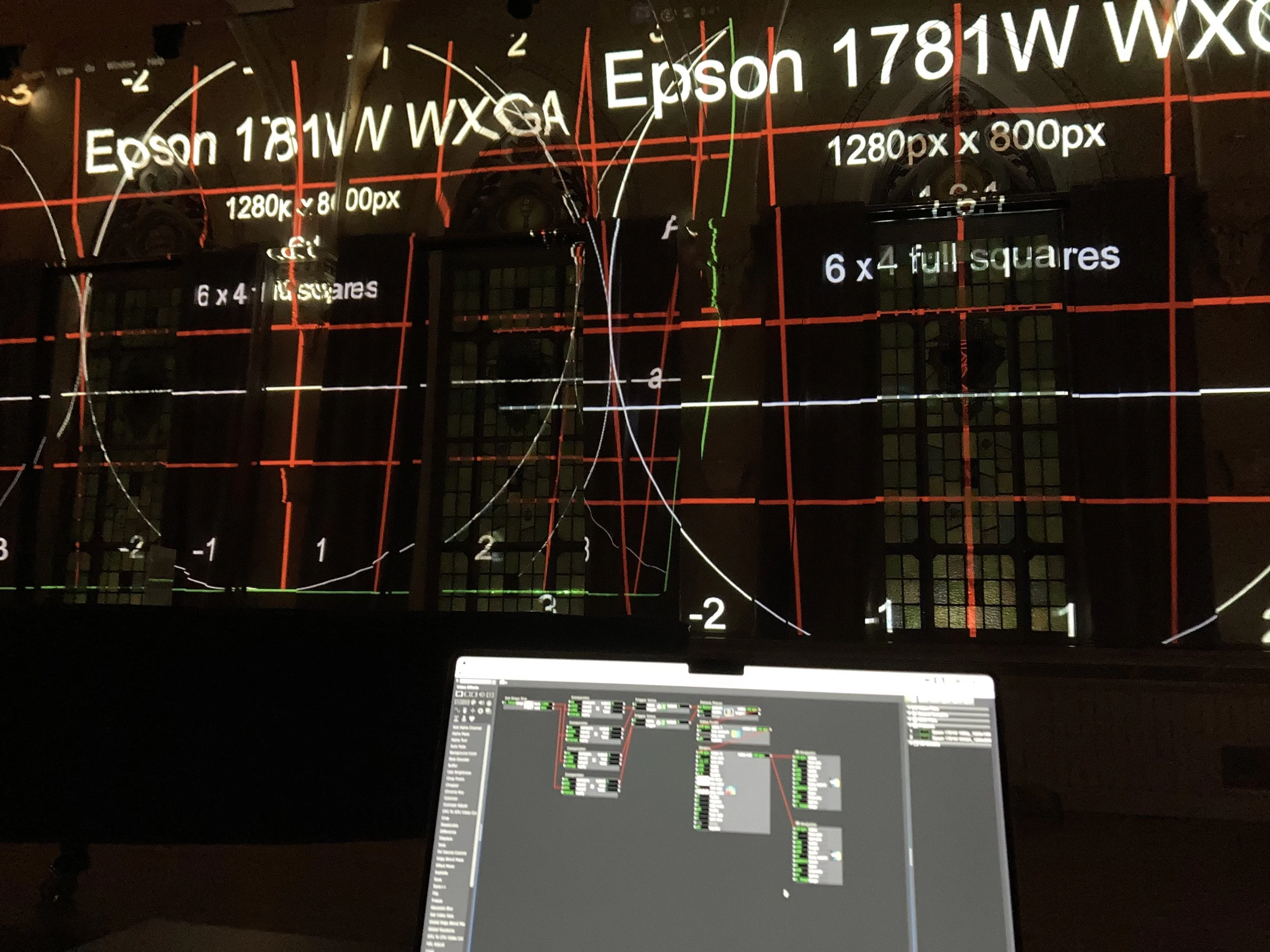
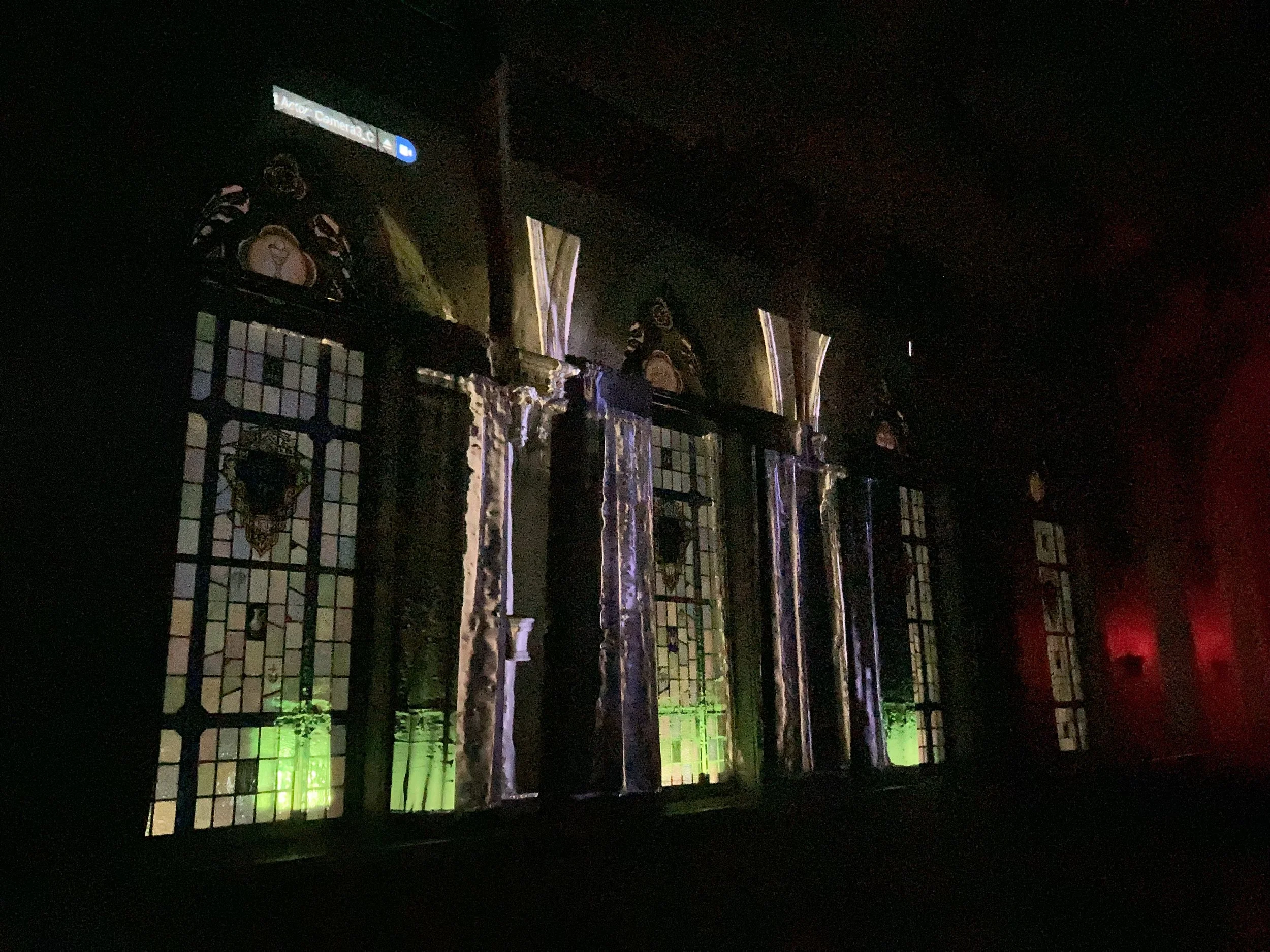
Since the projection sessions in Brooks Concert Hall, I’ve talked to a handful of coworkers and classmates about a third, public showing but just haven’t had the time to get it together. Looking back, we’ve had nine major productions at work in the past two weeks! I’m looking at the end of this coming week, possibly next for a showing for anyone who’s still around, and we’ve also unboxed and set up our four 12K laser projectors at work and I may take this as an opportunity to test these out! In theory, they’ll be brighter and I won’t have the lens shift issue to worry about.

I’ve also submitted my proposal for a Praxis project for next semester. My goal is to create an exhibit of interactive museum-style installations, based on some (as-yet TBD) fictional story. I have a handful of interesting installations/interactions sketched out, including wavetables, infrasound, and a couple options to finish and integrate my first-semester telescope project. I haven’t decided on a story to put behind these installations, though one of the finalist ideas is to investigate a race of nomadic time-wanderers, where only the things they carry travel with them in time. Another is Lucian’s Roman satire A True Story, which I spent a good chunk of the fall researching for just this sort of project. Yet a third idea would be to lean into my previous Masters research and focus on something from the Oresteia, or another ancient Greek story.

The next big interactive-media project on my docket is, however, much closer. With Clark’s semester now over and Holy Cross’s very nearly done, I get to turn my focus to Fresh Squeezed Opera’s next new sci-fi opera production, When He Was Good! It’s a story about a young boy with loving parents and an alien who pushes that love to the limit to determine the future of the human race. Blocking Rehearsals start in two weeks, I’ve now got an idea of what the set looks like, and I’m looking forward to a little bit of crunch to adapt my ideas to the set and make it all work. For obvious reasons I won’t post anything here besides my own work, but the new set has gone in a very different direction from what I was expecting and I really like it so far.

Further along, it also looks as though two of my Holy Cross shows next year might have a real video/media component, and while I’m looking forward to it, I also know that keeping both a lighting and media component in scope alongside running a Studio project will be a challenge.

Matthew Wasser
#26: It Works pt. 2! (4/11-4/17)

It worked again!

Second time around the setup went perfectly. Even though I’d struck the whole setup and started from scratch again, recreating the projector location was fairly easy (I brought a laser measure this time which saved some time). Projector #2, sadly, never worked out. The first night I came with my bag full of every cable, extender, adapter, etc. I thought I would need. This night I just brought what I knew I needed and, surprise, the 20’ HDMI cables I found in the hall didn’t work, and I hadn’t brought my own video extenders since I’d found these cables. It did work intermittently and I had the second projector connected for at least 20-30 seconds, but never even got it calibrated. Additionally was clear that the fixed vertical shift on this second projector did not have the same optics as the first, despite the fact that they’re “identical” models.

Other than that, everything went wonderfully. The single projector was quick to line up, setting up lighting states was straightforward, and they’d conveniently left a grand piano in the middle of the hall that I used to stage some photographs – looking back at last weeks, they’re great, but they don’t look that different from the unreal screenshots, since the only thing visible is the light from the projector, which looks about the same in a photo of real life as in a screenshot of unreal. I promise the real-life experience is much better, and hope that the piano in the shot brings some of that perspective with it.

I’m happy with the images, don’t terribly mind the lack of projector #2, and am eager to do it again with people around, although I may need to put that off for a little to get through the end of the production season at work, the end of Studio w/ RJ’s project, and all these blog posts that I’ve gotten so incredibly behind on…

Matthew Wasser
#25: It works! (4/3-11)

It works! I’ve done a night of projection mapping in Brooks concert hall, and while it took a few tries to get everything properly lined up, it all did.

I went in just before sunset, spent some time clearing the space, getting the tables out and setting the projectors up. The calibration patch was super useful to get the projector perpendicular to the wall and horizontal (the floor, it turns out, is not perfectly level).

After a few tries to match the right vertical angle and FOV, it became clear that, due to the lens-shift in the projector, the scale of the image on the wall was off in one direction. I couldn’t stretch the image in the camera and didn’t want to rescale the model again, so instead used the projector’s keystone & cheated a bit with the camera’s height & vertical angle. The keystone was fairly straightforward to adjust. When I set the camera to the distance, zoom and angle that it should be, the vertical lines of the image were not all vertical on the wall – they key stoned out at the top. I adjusted the projector’s keystone until they lined up, which left me with an image that was unskewed, aligned with the wall at the bottom of the windows, but also too tall. So I shifted the camera’s z-position higher and vertical angle lower until the distance between the easily-identifiable bottom-of-the-windows and easily-identifiable curtain rods lined up.

Similarly, eliminating the computer’s & unreal’s UI to match the camera’s FOV with the projector’s zoom was a little messy, but perfectly straightforward – I punched in with the projector’s digital zoom until it roughly lined up with the camera frame in the unreal viewport (particularly the bottom edge of the frame), noted the adjustments, and fine-tuned the camera FOV in unreal to match.

Both of these do have an image quality cost and would be ideal to do either in Unreal or using a video-processing engine in between Unreal and the projector, but the important thing is that it worked, and worked well. Even fine architectural details lined up perfectly, and once it’s all there (and the sun set and my eyes adjusted to the dark), playing around with the image was just fun.

The next step is to set this all up once again (hopefully much quicker now), do it again again with a second projector to map the whole wall, create a handful of lighting looks, and stage and take a couple photos showing the “lit” space.

Matthew Wasser
#24: Projection Prep (3/8-4/3)

Well it looks like I’ve followed up the slow week of PAX with a slow week of Easter Break. I’ve done my projector math, updated the unreal model, and built my projector-calibration izzy patch.

The projector math is fairly simple – the BenQ MW632ST projectors I have should sit just fine on a couple of 20” tall rolling tables and hit the top half of the wall. I will need to prop up the back a little, but that vertical angle is already so uncertain that I don’t see that making my life any more difficult.

I’ve re-scaled the unreal model so that one inch is 10 unreal units, using the 4’ wide windows as reference. I’m delighted that lighting all scaled perfectly well with the model, and I don’t seem to adjust the brightness to compensate for the slightly-larger throw distances. In the future, I could see it being very convenient to include a distinct reference object of known size in the scan – e.g. an 18” acting cube, somewhere that can later be cut out. We’ll see how accurate that rescale actually is.

The projector calibration patch is super simple, just the test images with a pair of 2-pixel-wide white lines that I can reposition (or angle) as needed.

And that’s all – at this point, I’m all set for projections in the space as soon as I and Brooks Concert Hall are both free after sunset at the same time. Which, given the coming tech week, will probably have to be Sunday.

Matthew Wasser
#23: PAX Week (3/20-27)

The main focus of this week has been PAX & RJ’s studio, and I’m afraid I haven’t made much progress on my own project. The idea that I’d use “down time” this week from work to do the final projection in the venue hasn’t really survived it’s encounter with reality. I have done a final 3D test and know what I need to do to get ready for that, but the final projection will end up being the final milestone (and the same week my show at Holy Cross opens too, sadly – it’ll be a busy one!)

First, I’m planning to project straight-on to the wall, rather than from two opposing angles. This does mean that some recesses of the wall won’t have coverage, but they’ll hit most of the wall, and do 90% of what I’m looking for with around 30% of the work. Fair trade. I’m also only planning to project on the upper portion of the wall (excluding the ~3’ radiator at the bottom). If this becomes part of a performance, that would be a challenging area to hit anyway with people sitting in front of the wall.

I do plan to use my wider, dimmer BenQ MW632ST projectors – they have the right optics, I can set them up on a set of rolling tables that are already in the hall, and the only downside is that they’re dim. Too dim for a proper performance with an audience and lit musicians in front, but just fine for a tech demo and photos.

I also know that I’ll need a projector calibration system, and have a rough idea for one that I can build in Isadora. This will let me check that the projectors are level, centered, and perpendicular to the wall (or at an angle if I change my mind), and give me a good reference for matching the projector zoom & camera FOV.

Matthew Wasser
#22: The Scale Model (3/19)

This week I’ve successfully printed the scale 3D model, and set up and run several lighting tests. Printing took a little over 9 hours, using a fairly high (.2mm) layer height. I’d have loved more detail (especially since this printer can do much better), but even a .15mm layer height would’ve taken a whole day to print. The Ultimaker S5 I’m using has a number of excellent qualities – it’s robust, reliable, can handle just about any material and is very stable – but speed isn’t one of them. If I were to have another go at it, I’d love to cut the sides down and scale the whole model up, run it at a .1mm layer height to get more detail, and plan to have it spend 2 days printing. What I’ve got is just fine for this project, though.

I’ve now done several lighting tests on the scale model, and it has been a little challenging to get everything lined up, but the process has been getting quicker, and results are at least functional. Doing this at a small scale makes it a challenge to get enough precision in the projector setup, and I’m hopeful that the full-scale setup will make that much easier.

The first time, I got everything roughly set up and did some trial-and-error to get the projector in the right place, but that was never particularly effective. I had much more luck setting measurements for everything I could – an inch on this scale model is about 341 “Unreal units,” and using that and a measuring square I’m able to position the projectors in exactly the right location and with roughly the right left-right angle (i.e. about the z-axis) this is much more effective, as it leaves me with the FOV and x-axis angle as the main variables.

The FOV is, unfortunately, really imprecise in this system, for two reasons. 1) while the camera is set to the same FOV and aspect ratio as the projector, it isn’t quite able to go properly full-screen. This means I need to “guess” a little wide and eyeball it. 2) the projector includes a vertical shift, and so I’ve tilted the projectors down to center them on the model, but this means that I really don’t know what the x-axis angle of the camera wants to be. Also, the projector’s built-in lens shift means that it’s, essentially, optically keystoned, and I doubt that can be replicated in Unreal’s cameras.

Still, I’ve been able to get the projectors sufficiently aligned, and while the trial-and-error for those two parameters does take some time, at this point can get it done in less than an hour. I’m certain that doing this at scale will be easier, since it means that my projector adjustments in real life will have much higher precision, but I’m not sure what other issues might come up.

Matthew Wasser
#21: Lights and Cameras (3/17-18)

This has been a great, productive weekend. I set up the cameras & full-screen viewports to route the video to projectors, used them to create a handful of basic lighting looks and fine-tune the lighting systems, and tested blueprint programming to create a cue list.

Previously, I’d gotten the new, cleaned-up 3D model in a new, cleaned-up Unreal file and set up the lighting systems that I plan to use. I did all of that work inside the scene that was created to import the .fbx file of the wall, but plan to leave the cameras outside that scene to make it easier to get clean views in the viewports without the orange “selection” highlight.

I set up 3 cameras – one face-on and one each at an angle from the left and right. I’ve also set up three new viewports on a second monitor, each ‘piloting’ one camera. The projectors will be at the left and right angles so that each projector fills in the ‘shadows’ where the other projector can’t hit, and the center camera lets me view the wall from the audiences perspective, and without the selection highlight.

The viewports have several useful settings to clean up the output – each one now has it’s toolbar hidden and both “Game Mode” & “Immersive Mode” toggled on. This isn’t quite perfect – there’s still a little menu icon in the top left corner, and while the viewport is piloting a camera, a fairly large “Pilot Actor…” label/button appears in the same area. Both need to be solved for a presentable, performance ready end product, but I’m happy to overlook for now and focus on the actual design & mapping.

The cameras have a ton of useful features (far more than I think I’ll need) and it’s very simple to set the aspect ratio and fov angle to match the projectors that I have access to. I’ve tested this with several lens options for the large, 12K lumen installation projectors I have access to at work, and the perfect lens optics fall right into the range for which we don’t actually own lenses. What we do have is either so wide, and would have to be so close to the wall that it won’t fill in all the detail in the architecture, or so narrow that it won’t cover the full width of the wall. I do have projectors myself with the right optics, but they’re not nearly as bright. The best solution I have right now is to focus only on a ~25’ chunk in the center of the wall, with the idea that a more-complicated, 4-projector setup could expand this to cover the whole wall. For now, the cameras are set up to match a pair of small portable projectors I can borrow from work to light the 3D model.

While I’ve got a much better system of controlling lights now that they’re sorted into folders, I’d love to be able to program each look I’m planning into a cue mapped to a keyboard key. I’ve taken a look at blueprint and some online guides and getting that functionality is basic and straightforward. Recording each cue might be a little complicated, but I’m not sure I’ll get that far. When running the “game,” these controls work absolutely perfectly… in only one viewport. Seems like a simple problem to solve, right? Sadly, no – it’s not hard to find other people online that have the same issue – apparently this is a feature of Unity, notably lacking in Unreal, and while there was a plugin to fix this, it was only in Unreal 4.

Faced with the options of migrating to Unity, migrating to Unreal 4, or just clicking the “visible” checkbox a bunch of times to set up the lighting looks like I’ve already been doing, I’ll stick with the last option. Long term, I’m sure there’s a way to get this all into something that will run with multiple full-screens and use blueprint as control but, again, right now I just want to make sure that this process will actually work.

Next up, I plan to have a working mockup using the scale model – everything is ready to go except the 3D print itself.

Matthew Wasser
#20: New Unreal Project (& 3D Model Work) (3/7-3/16)

I created a new unreal file this week, tried out a few file-management systems, and now think I’ll be able to have a 3D printed mockup to test with.

I added the cleaned-up model to Unreal, got the wall roughly aligned with the x-axis, and have filled in all of the light sources that I’m planning to work with. Right now, this is what that list looks like:

  • Wall Sconces Up: one very wide “spotlight” just above each of the 6 wall sconces, facing up. I wish this could sit inside the wall sconce, but would have to hollow out the wall sconces in Blender, and this works more than well enough for this experiment.

  • Wall Sconces Down: one very wide “spotlight” just below each of the 6 wall sconces, facing down.

  • Below Windows: 2D “strip lights” that sit at the bottom of each of the 5 center windows, a few inches in front of them to throw light up the face of the windows, adding color there and hopefully highlighting the shallow texture of each window

  • Above  Windows: A sharp, fairly narrow spotlight facing straight down above each stained glass window.

  • High Sides: spotlights from either side of the wall, at a shallow angle to the wall, originating near the top of the wall and scraping across and downwards. I’ve done this as a pair of lights (“near” and “far”), to cover the whole wall. One light further away could work just as well, but this way I can control the colors separately on each half. These lights do a great job highlighting the top of the curtains and the edges of the vaults.

  • Mid Sides: same as above, but more centered vertically on the wall, aligned near the top of the curtains. Separating near/far not so useful here. These lights are perfect to highlight the folds of the curtain, which I really hope line up with the curtains in real life.

  • Low Sides: Sidelights like the previous two, but these are located near the bottom of the wall, highlighting the curtain texture as well as the vaults above.

  • Box Booms: These lights come at the wall more form the front, and provide a “fill” light – whereas the sidelight lights very little of the actual wall, and mainly accentuates the details and edges, the box booms fill in the shadows and do a better job lighting the wall

  • Floating Ball: A loose omnidirectional light I can play around with.

The closest thing I can find to folders to put these into are what seem to be scenes. I’m disappointed that I can’t easily toggle all of the lights on and off together, or manipulate their color & brightness together, simply because they’re all in the same scene, however it does make it much easier to find all the lights I need. I’ve discovered that I can “favorite” visibility, and that makes building each look much quicker. I’m sure a Blueprint can do exactly what I want in terms of controlling multiple lights easily, but I’ll cross that bridge later.

All of these lights are inside the .fbx file in Unreal, meaning that I can move the model around and all the lights travel with it. All the cameras will be outside of the .fbx, so that I don’t have to worry about the orange highlight as much. As Nathaniel pointed out, the G key can hide these (by toggling “game mode”).

 In addition to the new Unreal project setup, I’ve got a printable 3D model to work with as well. After some (very) brief research, I’ve discovered Blender’s decimate function, and was able to more than halve the face count without loosing noticeable detail, and feel that I can go even further for a 3D print.

Rather than extruding the shape into a solid object, I’ve used a handful of Booleans to create a block with the face of the scan mesh. I also had to fill a number of holes that I’d created when I first tried to clean up the model, and ultimately replaced the beadboard lower wall section with a flat surface, since it had so many holes in it. Note to self – next time, don’t simply delete faces to remove protrusions, use a Boolean!. Regardless, I’ve created and sliced a model that I can print at work in a little over 9hrs. Not too long ago I was ready to give up on the 3D print component, but now it’s ready to print and I’ve gotten a much better mesh out of the process.

Matthew Wasser
#19 Niagara, or not (2/28-3/10)

This week I dove into Niagara, Unreal’s VFX system, on the hunt for a great flickering firelight to work into the wall sconces (and maybe other places too!). I’ve learned a lot about Niagara, how to build FX from scratch and how to create new FX, but so far haven’t been able to use it to do quite what I want.

First off, I did a quick search for a how-to on creating a flame effect in Niagara, found this one (in 12 minutes!! – it did take me rather longer myself) and had great fun building a flame effect from scratch and working it into the model.

I then discovered the default P_fire effect, included with Unreal, which did exactly the same thing. Great start. Regardless, I am glad I had the experience of making the effect myself, especially as I dove into the more-complex P_fire effect to try an convince me to show just the firelight and not the flames. I never did – as far as I can tell, the texture of the flames is what is emitting the light, and hiding or changing the flames particles (in any of the ways that I could try) also hid or changed the firelight.

Additionally, while changing the color of the standard light source in Unreal is a straightforward and only-slightly-cumbersome process, adjusting the color and intensity of the light from a Niagara effect seems to be something I need to do several steps (and go into the Niagara FX editor) to do.

I’m sure both of these are solvable issues, however the flame effect isn’t really necessary for the project to work, and not worth sinking any more of my time into.

Instead, I’ve moved on to start trying to get the 3D model printable. I’m not totally sure if that will be achievable either – the models are so high-poly that my slicer can’t even load (much less slice) it. I’ve had a go at extruding the model into a solid object, and unfortunately it’s clear that this isn’t quite the right tool for the job, and I’ll need to find a good chunk of time to spend on the 3D model if I want to test this on a 3D print. I did, however, discover that the model also still has it’s texture, and wonder if I can do that to help make the colors of the walls or windows pop a bit.

Matthew Wasser
#18 Cleaning up the 3D Model

The name of the game for this week is giving myself a good quality 3D-model to work with going forward, plus a bit of a crash-course in Blender. I’ve worked with Blender on one occasion in the past – I had to create a very particular UV map for a sphere to create a pseudo-360º camera live feed out of some mirrorless cameras w/ fisheye lenses. I think it’s safe to say that that’s not really useful experience to bring to the table here.

I followed the rough instructions from folks in the class to highlight and delete faces that were sticking out. This helped with some of the worse offenders, but there was still the matter of floating objects, and it also left the lower section of (flat, beadboard) wall a little uneven. For the former, I looked up how to delete loose geometry (not a huge challenge at all). For the latter, Booleans turned out to be the way to go. Turns out this is something I’ve done quite often building models in Sketchup, and now I finally understand what Booleans are after hearing Nathaniel and RJ talk about them as (an imperfect but very effective) part of the racing car design process in studio. That was a wonderful moment.

I’ve also taken the chance to better align the wall with the x/y/z axes, and deleted the default camera and light source that Blender starts with – this camera, I realize, was the one inside the .fbx in my first lighting attempt (which was not super useful because of the orange selection highlight that came up whenever the camera was also selected.

In the end, the mesh from the scan of the hall is now cut down to just the useable parts, and I’m looking forward to starting over entirely with this newer, cleaner model into a fresh Unreal project with some better file management.

Matthew Wasser
#17 First Lighting

This week I took the 3D scan from last week, added it to a new Unreal project, and took a first pass at lighting it in the engine. While I’ve got a whole list of minor issues and problems to look into and fix, overall this has been fairly intuitive and a ton of fun to play around with. 

I did have to convert my model to a .fbx to get it into Unreal. I’d downloaded an .obj file from the Kiri app since it’s one of the format options that I’m the most familiar with, but found that I wasn’t able to import that type of file into Unreal. I used Blender to convert it to a .fbx, which worked fine. I suppose in the future I should just download a .fbx to begin with. 

Once it was in unreal, positioning and lighting the model was both intuitive and fun. Unreal has a handful of options for lighting sources, including the sun, omnidirectional light sources, spotlights, 2D lights, and directional light. 

The Sun: Dropping the model in, adjusting the “solar time,” and lining up the model was the gateway drug of lighting in Unreal. It’s easy and beautiful and I can’t wait to see what it looks like on the wall in real life.  

Omnidirectional light sources are fun to play with, and are easy to pick either a color or set a specific “white” by color temperature. 

Spotlights are directional, and in addition to all the settings of an omnidirectional light, you can set a beam and field angle, and I’ve found these to be the most fun to play with. They’re great as sources for the wall sconces, as well as off to the side, and have the advantage (over their real-life counterparts) of having, essentially, infinite brightness.

2D lights are a rod of omnidirectional light in a set length, and fit great as a strip light below each window. It would be great if they could be directional too, but at the moment that doesn’t seem to be an issue.

Directional Light is confusing. It definitely washes the set in light, but I haven’t quite figured out where it comes from or how to control it.

In addition to the lights, I also used the existing camera to try lining up some projection angles. These cameras have a ton of features, letting you set basic stuff like FOV, but also a ton of details that would mean a lot to me if I did more cinematography. There are two cameras in this – one is inside the .fbx, and whenever I use that one there’s an orange “highlight” around the edges of and sometimes in the middle of the mesh that I don’t want in a projected image. Fortunately, there’s also a camera that’s not in the .fbx file and that one doesn’t include these orange lines.

I made a collection of first looks to experiment with these sources and the engine, ran into a ton of fun issues, and have a long list of questions to ask and things to do differently on a second pass at this.

Issues:

  • Model has floating blobs and other details (this currently causes unrealistic shadows in sunlight, and will definitely be a problem when 3D printing a scale model)

  • The model is just a shell, w/out any depth, and so isn’t printable at the moment and I’ll have to learn a bit of 3D modeling (probably in Blender) if I want to make that happen.

  • I wasn’t able to import an .obj file. This wasn’t a big issue, but is kind of surprising and I’m curious if I’m doing something wrong.

  • Object was not perfectly lined up with an axis when I started, which meant that duplicating sources along the wall took a bit of finesse (whereas, if the object were perfectly aligned with one axis, I would be able to single-click-and-drag to duplicate light sources along the wall)

  • Sunlight shines through the backside of the model. I’m sure there’s an easy fix for this, although making it a 3d-printable model likely be one.

Matthew Wasser
#16 First Scans

At this point I did several test scans with a couple possible apps, found one that I’m reasonably happy with, and have made a couple of scans of the venue!

This video was a great resource, offering a comparison of several apps from an architectural projection mapping perspective. Specifically, it wound up suggesting Kiri, WIDAR, and Pix4D Catch. So far I’ve tried out Kiri and an app I’d already had some experience with, Polycam. Polycam never gave me a good result, but Kiri’s been surprisingly effective.

This video also offers a comparison of LiDAR and Photogrammetry, and leads me to the conclusion that photogrammetry will likely yield better results than LiDAR. I’d certainly give LiDAR a try if I had a device handy, but by both this and the above account, I don’t think it’s worth the time to track down and borrow a LiDAR phone.

I did some test scans last week using the in-progress set of Oklahoma! (The Holy Cross Theatre Dept. show that I’ve just finished a lighting design for). The one with Kiri came out surprisingly well, and so I decided to move forward with it. I’ve paid for a month’s worth of the “pro” subscription, which increases the number of photos that I can use in a single scan, and have done two scans with it of the hall itself

The first set of scans had some noticeable quality issues, but came out surprisingly well all things considered. The surfaces themselves were rough and it lost a ton of detail in the ceiling vaults, the cornices, and the wall sconces between the curtains. Not bad, but not great either.

Based on that first scan and its’ issues, I’ve done a second one with several improvements. First, I took the photos on an overcast day, where there’s still plenty of ambient sunlight for the photos, but the windows themsleves aren’t too much brighter than the room. Second, I turned the lights on. The lights themselves are all focused on the stage area, but the set of front lights facing the wall from across the bounced pretty well off of the light, glossy floor, so I stuck with those and left everything else off. I also focused more specifically on the areas that were the 3D model came out rough, using more close-up shots and fewer far away shots.

I’m super happy with these results, but am also weighing a third pass using a DSLR for even more detail, and with attention on the few areas that still look blobby. The areas I focused on before (like the cornices and sconces between the curtains) have an incredible level of detail, but there are some areas (like the bottom ledges of the windows) that I didn’t take enough clear photos of.

After this, I have found a couple guides to follow on getting this into Unreal, and hope to give that a try over this coming week. I’d love to take advantage of the computers in MACD, but my Tuesday off looks like a 11”-14” snowstorm. I am looking forward to the snow, but I’m also not planning to leave my house, so I may just spend the time figuring out what I can get done on my laptop.

Also I’m already quite behind on these blog posts, but have some time set aside to catch up over the next couple weeks. Oklahoma! is open! It’s easily the largest and most complex lighting design that I’ve done to date. While all did not go smoothly in the lighting world, and getting to the finish line took just about all the time I could throw at it, it’s come out well and has been an intensive learning experience I can’t begin to quantify. It’ll be running for another week! I imagine I’ll have the good pictures from our photographer by the next blog post to throw in.

Matthew Wasser
#15: A New Project

The new semester also comes with a new Seminar project for me – I’ve decided to move forward with the projection-mapping idea. Specifically, my plan is to try out a fun new workflow of creating video projection designs, using a game engine and a 3D scan/model of the “surface.” This video is ultimately the inspiration here – I came across it years ago and it’s stuck with me (although I did have to spend a couple days trying to track it down again).

I do have a venue in mind - Brooks Concert Hall! It’s a beautiful ex-chapel at Holy Cross where I work, and definitely deserves some beautiful atmospheric lighting. It’s been through a a lot in the past century-and-a-half, but what’s now the wall behind the stage has a set of restored stained glass windows set in gothic arches with curtains and wall sconces. It’s got a mix of large flat surfaces, deep texture, and different light sources that are all great opportunities to work with.

My goal here is to make a 3D scan of this wall, put that model into a game engine, light the model, and then capture the in-game lighting in several places to turn those into a projection mapping back on the wall in real life. I’m hopeful that these looks will be part of a performance I’m working towards over the summer, and will also be a chance to trial this workflow that, if I can familiarize myself with it, will be a great bridge between my projection-design plans and current work as a lighting designer.

The milestones I’ve planned are:
Project Description: Atmospheric projection mapping using a 3D venue scan in a game engine
Milestone 1 (2/7): Use photogrammetry to create a 3D Model of the venue. Also plan 6-8 different lighting looks to create.
Milestone 2 (2/21): Print 3D Model from Milestone 1 for testing. Create first lighting look in game engine.
Milestone 3 (3/20): All lighting looks finished.
Milestone 4 (4/3): Setup projectors, run performance, take a video
Milestone 5 (4/17): Outline plan for studio project

Description of completed work:
This project will allow me to try using a game engine to create atmospheric lighting looks for projection mapping. The projection mapping itself is also an opportunity to develop creative craft (along side those technical skills), and will serve as a portfolio piece. I'm hopeful that this will lead towards a studio project involving projection design, and in particular create a workflow that would allow collaborators to better leverage a game-design skillset to create video designs for live performance.

Matthew Wasser
#14 Spring Seminar Ideas!

I’m looking at all my options for spring seminar courses, and they fall into a few categories:

  • Continue the telescope project with some changes

  • Start a new projection mapping project

  • Prepare for Praxis project


In the first category, there are a couple ways to tweak the telescope project to spend more time focused on the media aspect. Essentially, I can shuffle the order around so that I create the media elements first, and use a phone or something as a mock-up, and then wind up with a functional-but-incomplete mock-up rather than a completed-but-non-functional prop. Trading out the custom electronics for a phone embedded in the top would also both simplify the telescope and shift the focus away from the prop itself. Either way, the first thing to go would be the fun paddle system.


Looking at new projection & video-design focused projects, this is a perfect opportunity to try out a couple new workflow ideas. Years ago I stumbled on an example of a projection designer scanning the set, loading it onto a computer to render lighting, and projecting the rendered results back onto the set – imitating different (and impossible) lighting environments. That’s something I’d love to explore, and at Becker I’ve got plenty of experience around me to work with to figure out what problems and solutions that might lead to. Project-wise, a few options stand out:

-       Holy Cross has a beautiful old chapel that now serves as a small concert hall with beautiful architecture and decoration that would be a brilliant projection surface. A co-worker and I have been talking for years now about projection-mapping the space, and this is the perfect opportunity.

-       I’ve signed on to provide a video design for an opera in New York this June, and while I’m not sure about what it will involve just yet, it could be a great personal project to spend some consistent time on over the course of the semester.

-       Two spaces at work are each a great opportunity for a semi-permanent projection mapping setup. There’s a lobby space with great wooden overhangs that are a perfect surface for projections, and a concert hall with a beautiful wooden shell that, while simple, is a great canvas for some “stock” projections for performances, etc. in the hall.


The final option, preparing for a Praxis project, stands out as a chance to get ahead of the curve on a possible, small interactive theatre event. Seeing the Interactive Theatre class’s Somnus last week was wonderful and inspiring. I’m impressed at how the wide variety of elements came together in the space. I wasn’t sure how well it would drag me, or any audience members, into it’s world, but it did! I was particularly dragged in by the puzzles, another person I was with was really into trading for items. The structure of the event included some time pressure too, which meant that I felt like I had to pick between spending time working on this one particular puzzle I encountered, or following other routes that would work us towards a “good” ending.

            One of the challenges that I see turning that into a project for Studio is coming up with a plan & story that’s specific enough to give collaborators a framework to work in, but flexible enough to accommodate whatever skills and interests they have and want to develop in the class. In some ways, I’m leaning towards developing an open-ended concept that could be realized as an interactive theatre show, but could be adapted to suit the skills of whoever I have to work with. That’s something I feel I need to spend some time developing regardless of it’s status as a seminar project for the spring. That said, there is a bit of middle-ground between all 3 projects – having a workflow to create theatre projection mappings with a 3D environment would make it easier for someone with experience in 3D environment design to use those skills in a live performance context. And in a larger sense, the satirical fever-dream of an Ancient Greek story that’s been an inspiration for this telescope project definitely comes to mind as an inspiration for an interactive theatre project too.

All in all, I’m looking forward to spending some down time over the holidays letting this all process, and getting as much advice as I can on where this all might go.

Matthew Wasser
#13 Presentation & Ideas for the Future

The last step in this semeseter’s process (or penultimate, depending on what next week’s blog post wants to be about) is focused on where this project sits in my life, in this MFA that I’m pursuing, and in the next semester.

Creating the final presentation is a great chance to look back on where I started and everything I’ve had the opportunity to get back into as part of this project, and I’m so grateful. I’d long since fallen away from modelmaking, woodworking, props design and even the simple Sketchup-based 3D modeling I used to do. And in a different direction, I’m also glad to have the chance to dive into a bit of Ancient Greek & Roman literature, art and technology.

There’s also a lot left to look forward to on this project – 3D Printing and learning how to use a CNC, small electronics and possibly programming with an Arduino and, eventually, some creating some kind of interactive multimedia design component to tie it all together. That last “eventually,” however, is where the issue lies. Laying out the next semester’s worth of work, a possible set of milestones could be:

  1. Finish wooden telescope body

  2. Learn how to use CNC and create paddle carrier

  3. Assemble and test electronics outside of machine

  4. Assemble and test electronics inside machine

  5. Add “interactive media” element

Assuming I see this through in it’s current form, I’d only get to the interactive media content near the end of the semester. Even if I combine the first two milestones, I’d still only get one “revision” of whatever it is this telescope is supposed to do. It would still be fun, but I think it makes sense to be more selective about what I spend my time learning and doing.

First, I want to build something in Isadora. This is software I’m familiar with, but still have plenty to learn about, especially when it comes to physical interactive controls. That’s the second focus I want to prioritize – I’ve looked into three interactive human-interface devices this past semester (Makey Makey, Arduino and I-CubeX) and want to spend some solid time implementing at least one of them as an interactive control, nominally to an Isadora project. And third, to tie it all together, I’d love to find a way to work collaboratively with other people. The current project is pretty isolating, and if my sprints were more on a “how do I tell this story” track, I know I’d get better (conceptual and technical) feedback from those in the MFA cohort, and so too would it be an avenue to reach out to others outside. If, for example, I stick with this Roman satire story I’ve been toying with, I know plenty of experts in classical literature that could weigh in. I may be a little inspired by Mark’s R&D direction here, and it’s something I’d like to be a part of this.

Based on that, the most straightforward options would be either to reorganize the milestones to work on the electronics first, and accept the risk that the physical aspect of the telescope might not be finished. Taking that a step further, I can also take steps to simplify the telescope and maximize the time spent on the media element, hopefully still using the telescope body itself.

I’m still compiling options that are a departure from the telescope project entirely, and the first one that comes to mind would be a projection mapping project, or a series of them (on Clark buildings, landscape, somewhere in MACD maybe, or even other places nearby). I’ve done some smaller versions, and plenty on theatre sets, but never anything interactive. And on that topic, I’m also curious about any performance projects going on that might want an interactive media component – theatre, dance, music, and there’s this musician I know we’ve talked about some fun music video ideas in the past.

Matthew Wasser
#12 Weathering and Assembly

Next up – adding the weathering and “external details.”

I smoothed out any and all corners pretty aggressively with a random orbit sander, and in particular added a bevel to the edges of the inset on the top of the telescope, and had a go at turning some minor construction issues into immersive time-worn blemishes. Some worked, some didn’t, and I think another pass is warranted at some point. there’s a couple corners of the main body that didn’t quite join properly – the sander wasn’t enough to fix them, but if I hack a chunk off with a circular saw, and then give it another pass with the sander it might look more natural. It also might severely damage the model, and either way is hard to do safely, but it is an idea. Sadly, I didn’t take photos in this process, but the results are in the following photos.

The next project was the yoke attachment, and true to my earlier concerns, bolting through the paddle carrier chassis (what I’ve decided to call the front-of-the-telescope part that the paddle carrier drops into) didn’t really provide a strong joint, since the main body of the telescope isn’t firmly attached to the paddle carrier chassis at all. Plus I’m concerned about the sideways tension breaking the glue joint between the blocks and the base of the paddle carrier chassis.

On the plus side, however, bolting only to the main body of the telescope works just fine! the large fender washers and an added wooden block spread out the force holding the telescope in place, and even with the overly-heavy block of wood on the front and some extra weight in the back to balance it out, the bolts don’t need to tighten enough to damage the wood.

After that, the last component I have time to add on is the strange greebly dish on the side. The original plan didn’t provide enough of a surface to attach any of the pieces together, so I added a couple extra blocks in the joints and it works well enough. I also elected not to try and cut a perfect circle, but went with a wonky octagon that seems to fit the telescope just as well. I’m not completely satisfied with the strength of this part though – I added a drywall screw and some blocking on the inside of the telescope to give it a better joint there, but I’ll have to judge it when everything’s dry.

Ultimately, I haven’t had the time to source a handle and cut out the paddles. These portions I’ve focused on are the priority and where the main challenges lie (as far as I can predict), and so have given me the info that I need to better plan the rest of the project. As I start thinking about the rest of the project, however, I notice that most of the work ahead for the next semester will lie in nailing down the electronics, and I’m not sure that that’s the best place to focus.

Matthew Wasser
#11 Shop Work

The wooden version of the telescope body is assembled! The main body is there, with a removable section for the paddle assembly and the screen/dial on the top, and a decent cavity for any electronics. The main priorities before Wednesday are to attach this to the yoke & base, add the handle, and add the strange dish-like thing on the other side that I still don’t have any purpose for in mind.

Constructing this has been surprisingly fun – I’d forgotten how much I liked woodworking. I used to do a fair amount of it in my more general previous job at Holy Cross, and this is a very welcome return to those skills. That said, this is much more of a precise project than I’m used to –

I started off with the main body of the telescope. Most of the pieces are cut from a 1/2” thick sheet, but I used a chunk of 3/4” ply for the bulkhead where the paddle assembly would slot into place for some extra strength. The whole thing is glued together – and given that I wasn’t going to take the shop’s clamps home with me I wrapped it in some tape to support the joints while they dried. I cut the window out freehand with a skill saw, and it did come out a little rough, but I think some weathering w/ a sander before it’s done will help deal with that.

The body needs two removable pieces - a back, to access the electronics and a top, to hold a screen and encoder. I added a handful of blocks to give the back something to rest against and to create a slot for the top piece to slide in and out. Granted, the top won't be removable once the encoder is installed, but it will still make it easier to add it and the screen in later, and make any adjustments to those components. Everything is friction-fit - these components don't need any fasteners to hold them in place, and in fact I need to devise a I better way to pop the back off - right now, the only way I can do that is by sliding the top panel backwards to push it out. That all bodes well for it holding up to human interaction, though.

The front of the telescope followed the same general plan that I started off with, but I reworked the details and construction method. It's still built around a to-be-cnc-milled paddle carrier, but whereas the paddle carrier itself was the main structural component before, with the sides and bottom attached to it, I've built it as an open chassis that the paddle carrier can drop into. The carrier itself is still needed to fit the front of the telescope in place, so I've cut a 2x6 down to the right size (and may as well use it to mill out the final assembly in the future).

All told, it has the practical upshot of being both modular and stronger than the original idea, and with a possible future advantage. I cut the bottom of this assembly down in line with my original plans, and only after realized that it could extend all the way to the back of the telescope, and hold all of the electronics for the telescope (save the screen and encoder on top). This will make the whole thing much simpler again in the final version. My only concern is the strength of the joint between the side walls and the end-grain of the plywood base, but so far it seems strong enough.

My plan is for the yoke attachment to also hold the two halves of the telescope together. With this new modular design, it doesn’t make sense for that to mount directly to the paddle carrier, so instead I’ve added a pair of blocks to the chassis for those yoke bolts to pass through. Since this will take some weight and is a joint to the end grain of the blocks, I’ve added a drywall screw to help strengthen the connection. Now that it’s done, however, I do have some doubts about it’s ability to do that job in the first place – with the gap between it and the wall of the telescope, tightening a bolt to the block probably won’t provide a strong connection & tilt joint.

With that, the mock-up of the main body of the telescope is done, and with several great improvements on top of it. At the time I’d wished that I had jumped straight to this point after the foam-core model, but now I do see the evidence of all the iterative improvements I’d made in the 3D model – each of those mistakes and problems to solve would’ve been painful to do with a physical mock-up too. What’s next at this point are the attachments – yoke, handle, paddles, and that strange dish-like object I stuck on one side.

Matthew Wasser
#10 Construction Prep

Telescope Project

I’ve fallen a bit behind on the blog posts, but am catching up! This will cover from the previous post until the start of this week on 11/20. In that time, I gave the penultimate sprint presentation, made some tweaks to the design based on it, and have started getting ready to construct a v2 telescope out of wood.

I have made a few updates to the design. Finding the right design for the handle wound up being a real challenge. I came up with several ideas I wasn’t happy with, went over them with the class in the presentation, and with their help realized that the handle doesn’t need to be ancient or match the rest of the telescope. It works just as well as a modern (or other) addition, and overall the feedback I’ve gotten inspires me to embrace a wider variety of ages in different components to this device. Another idea from the group in that vein is to include a chaotic rat’s nest of cables connecting the device to the brain and maybe other odd things. Partly to conceal the functional cables, but also to create an appearance of generations of people modifying and building on the device.

I ran into a couple minor issues getting my 3D printer set up after a couple months of inactivity, and opted to skip the agita of printing a second mockup, and just build the next version out of wood. It’ll be great. Based on that plan, I’ve laid out all the pieces w/ measurements to cut out of a single sheet of nicely-finished half-inch plywood that I’ve also gone and picked up from a local hardware store, and set aside some time to pop into the scene shop at work to put this all together.

I’ve also encountered an interesting inspiration for a what this device might plug into. At the Museum of Natural History in New York, I encountered an interactive video exhibit about climate change, and thought that the style, content and interactive elements all worked together perfectly. The technology isn’t particularly complex – in fact I could recreate it myself fairly easily with the right equipment – but as a total experience it really works. It’s something I’d love to try my hand at remaking overall, and some aspects of this could be a great way to see through the telescope.

Other

Outside of the telescope project, a lot’s been going on. At work, the lighting team of one is now a lighting team of two, and we’re more productive than ever before. Good Person of Setzuan has closed and we’re in the process of changing the space over for a student-run fashion show. We ran one last year and it was one of the most popular events at the performing arts center. We’re in an even better place this year, since our damaged lighting has been returned and we’re almost up to our full inventory. I’ve also started working on the next major Theatre Dept. show, Oklahoma! – and at the moment am weighing the opportunity to projection map a very fun set with the time it will take on top of everything else going on.

 We’re also prepping for some pretty major facility modifications to accommodate a touring dance company in January. Our 100A 3-phase company switch may not provide enough power for the scale of the rental equipment package they’ll require, and we’re looking at options to upgrade or augment it with an additional 100A of 208V 3-phase. We’re also planning to rewire an architectural house light system into multiple zones, which won’t be a minor job either.

And to top off the chaos, I’ve been helping my girlfriend buy an EV! It hasn’t been a stress free situation by even the most stretched imagination, but we’ve got it now, it’s a wonderful experience, we’re currently testing it out on a road trip to Maine. I love my own car, but this is definitely a more comfortable experience.

Matthew Wasser
#9 More Fine Tuning

Telescope Project

The revised telescope design is almost done! All the important components are modeled and fit together, and could be reasonably constructed. I’m considering simply 3D printing all of these components at a smaller scale, to more easily produce this next mock-up and test construction.

I’m still weighing some options for the “pan” encoder, which likely needs to be located outside of the telescope and in the base. This is the only component that I feel a real need to work to “hide” — all the other electronics will, with some work, fit comfortable inside the telescope body. I’ve settled on building a large housing over the bolt that attaches the yoke to the base, concealing an encoder inside. I can then either conceal wires connecting that object to the telescope above, or… not. With the right aesthetic, some kind of cable there could work just fine.

Though I didn’t go with them here, I have “vented” 1/2” bolts, which have an 1/8” tunnel in the center I could use to run cables through. In this case, those cables could then connect to an encoder concealed in the base of the entire telescope, but that would mean I’d need a substantial base. They may be useful to get cables into the telescope through the hinge, but that would be more for style than out of necessity if so. (these could also work, but just seem flimsy).

Instead of that hollow bolt option, I’ve discovered some low-profile encoder options that should fit decently in some kind of knob or object at the center of the telescope’s yoke.

I also have not yet decided on a handle design. I’ve looked at cabinet handles, door handles, pottery handles (including plenty of ancient Greek and Roman options), and so far nothing feels quite right. I think I may just have to pick a temporary design and revisit it later on in the process.

One other change is a design of an obviously-plastic shroud to hold the telescope body. I rather like the idea that this might have been something carried, and that the yoke mount is an artifact of more contemporary scholarship. If so, rather than drill holes in the artifact, they surely would have simply mounted it in some sort of holder.

All that remains before the end of the sprint on Wednesday is to model that object, decide on a handle design, and design a paddle. It’s a little tight but now that Good Person has opened I can spend a little more time on it.

Matthew Wasser
#8 Detail Work

Telescope Project

Since the last post, I’ve focused on revising the design and turning it into something that can hold the electronics, be built, and look the part. At this point all the important changes based on the construction process of the physical prototype are in the new 3D model, most of the components are build-ready, and I’ve started combing through photos I’ve taken for references or simply images to include in the final product (I’m branching out a bit from ancient greek art to all the ancient art I’ve photographed, but I think this works). Progress is slow at this point, but the next few weeks will be a chance to catch up.

I’ve also officially revised my milestones – for the current 4th Milestone I plan to finalize all these design updates into a revised design, and for the 5th Milestone construct a second prototype – this time with respecting the construction methods, space for electronics, etc. In some cases, this may be easier to build out of final materials, but I do expect to 3D print a few parts as mockups. The designs I have are already printable, so realizing them this way is likely the fastest method.

The Good Person of Setzuan

Where progress has been slow on the telescope project, it’s really picked up on the production of Good Person of Setzuan at work. The set is beautiful, first of all, and a joy to light. It’s been a real challenge to make this show less of a commitment than the previous semester’s productions. While it’s paid off in the personal time I have to work on the telescope project, RJ’s game project, and little things like doing laundry and celebrating my birthday, it’s also tough seeing where I could’ve done more. There’s only a few moments where the light really falls short, but they’re all fixable.

Matthew Wasser